Explore how dense copper fins, multi-pass tubing, and configurable connections deliver compact liquid-to-air heat rejection for lasers, power electronics, industrial equipment, and custom thermal systems.
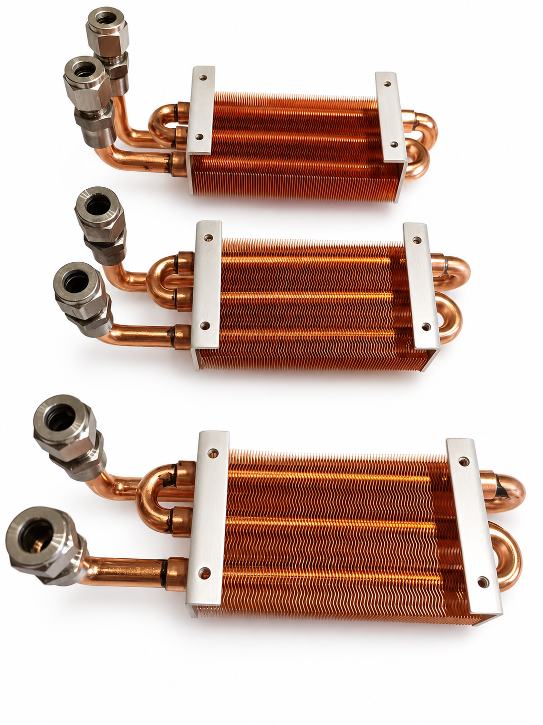
The USUSTK copper tube-fin heat exchanger is designed to transfer heat from a circulating liquid loop to ambient or forced air within a compact installation envelope. It combines copper coolant tubing, a densely packed formed-fin core, multi-pass return bends, external fluid connections, and integrated mounting rails in one application-specific assembly.
Rather than treating the heat exchanger as a stand-alone catalog component, the design can be configured around the equipment in which it will operate. Core dimensions, tube routing, fin geometry, connector orientation, mounting position, and allowable pressure drop can all be evaluated against the actual coolant, fan, pump, thermal load, and available space.
This makes the product suitable for engineers who need more than a nominal cooling-capacity figure. The objective is to deliver usable heat rejection at the system’s real operating point—without forcing an oversized fan, excessive pump power, or a difficult mechanical installation.
Heated coolant enters the copper tube circuit and travels through several passes across the fin core. Heat conducts through the tube wall and into the surrounding copper fins. Air moving through the fin channels then carries that heat away from the assembly.
Each visible element serves a thermal or mechanical function:
• Copper coolant tubes provide a conductive path between the liquid and the fin field.
• High-density formed copper fins expand the air-side surface area within a small core volume.
• Multi-pass U-bends distribute the coolant path across the available fin area.
• External threaded connections simplify integration with the customer’s liquid loop and can be configured for the required hose or piping arrangement.
• Mounting rails support repeatable installation and help isolate the fin core from assembly loads.
The result is a compact liquid-to-air heat exchanger that can be installed remotely from the primary heat source. A cold plate can absorb heat at a laser, power module, semiconductor process component, or other temperature-sensitive device, while the coolant transports that heat to the exchanger for rejection to air.
On the air side, available surface area is often the main constraint. The dense formed-fin core places a large amount of copper surface in contact with the airflow, helping the exchanger use its available volume effectively. The fin profile also influences airflow mixing and boundary-layer development, both of which affect convection.
Fin density must still be matched to the fan. Tighter spacing can add surface area, but it also raises air-side resistance and increases sensitivity to dust. USUSTK therefore evaluates fin geometry together with core depth, target airflow, available fan static pressure, acoustic limits, and the operating environment.
Copper’s high thermal conductivity helps spread heat from the tube contact region into the fin field. A copper tube and copper fin core also reduces the material discontinuity along the primary heat-transfer path. Consistent tube-to-fin contact and controlled joining are essential: additional fin area has little value if local interface resistance prevents it from becoming thermally active.
The multi-pass tube arrangement allows coolant to travel across the core and use more of the fin area. However, tube length, internal diameter, bends, fittings, and coolant properties all contribute to pressure drop. More passes are not automatically better.
For this reason, the circuit should be reviewed against the pump curve and the full loop resistance. Tube diameter, number of passes, series or parallel routing, and connection layout can be adjusted to balance coolant velocity, heat transfer, pressure loss, and temperature rise.
A heat-load value alone is not enough to define a suitable heat exchanger. A useful technical review also considers coolant type, liquid inlet temperature, ambient-air range, target flow rate, allowable temperature rise, fan performance, pump capability, pressure-drop limits, installation space, and airflow direction.
Installed performance can differ significantly from catalog component ratings. Airflow decreases when a fan must overcome the resistance of a dense fin core, enclosure grille, or filter. Coolant flow also changes after the pump is connected to cold plates, hoses, valves, fittings, and the heat exchanger. USUSTK therefore configures the tube circuit and fin core around the actual cooling loop and installation conditions instead of relying only on nominal fan or pump values.
The product can be developed around the following requirements:
Engineering input | Configurable product feature |
Heat load and target coolant temperatures | Core face area, depth, fin geometry, and tube circuit |
Coolant type, flow rate, and allowable pressure drop | Tube diameter, number of passes, and routing arrangement |
Fan airflow and available static pressure | Fin density, fin profile, and core thickness |
Equipment envelope and airflow direction | Overall dimensions and core orientation |
Hose or piping layout | Connection type, size, position, and direction |
Mechanical assembly requirements | Mounting-rail size, hole position, and installation interface |
Industrial environment and service interval | Fin spacing, material compatibility, cleaning access, and validation plan |
This application-specific approach helps avoid late-stage compromises such as rerouting hoses, changing a fan after thermal testing, or accepting excessive pressure drop because the heat exchanger was selected only by external dimensions.
The performance and reliability of a tube-fin heat exchanger depend on repeatable manufacturing, especially at the tube-to-fin interface and every fluid-circuit joint. USUSTK uses the following production sequence for this product:
1. Fin insertion: Formed fins are positioned and the copper tubes are threaded through the fin pack to create the heat-transfer core.
2. Tube expansion: The tubes are expanded to establish close, uniform contact with the fins, improving heat conduction and stabilizing the core.
3. High-frequency induction brazing: Return bends, connectors, and required tubing joints are joined by high-frequency induction brazing. A high-frequency alternating electromagnetic field induces eddy currents in the workpiece, rapidly heating the joint area to the brazing-filler melting temperature within seconds. Capillary action then draws the molten filler metal into the joint clearances, forming a secure, leak-tight multi-pass coolant circuit.
4. Grinding and polishing: Brazed areas and exposed surfaces are finished to remove excess brazing filler metal, improve appearance, and prepare the assembly for subsequent inspection and surface treatment.
5. Air-tightness testing: The completed circuit is checked for leakage before surface treatment and final assembly.
6. Cleaning and passivation: Processing residues and surface contaminants are removed, followed by passivation to improve surface cleanliness and oxidation resistance.
7. Helium leak testing: A sensitive helium-based leak check is performed to identify fine leakage paths that may not be detected during routine air-tightness testing.
8. Assembly and laser marking: Mounting parts and specified accessories are installed, and identification or traceability information is laser marked according to project requirements.
9. Final inspection and packaging: Dimensions, appearance, interfaces, marking, and overall assembly are verified before protective packaging.
This controlled process helps maintain uniform fin spacing, stable tube-to-fin contact, clean fluid passages, and reliable sealed joints. Test conditions, acceptance criteria, marking content, and inspection records can be defined according to the coolant, operating pressure, lifecycle targets, and customer standards.


